Crop Circle Audio

Would you like to react to this message? Create an account in a few clicks or log in to continue.
Crop Circle Audio

The purpose of this forum is to create a community that is focused on fabricating the best open source headphones in the world for as little money as possible using only free time.


2 posters

    CCA-1 the ECR-Ortho

    khbaur330162
    khbaur330162
    Admin


    Posts : 23
    Join date : 2016-03-06
    Location : Chicago Suburb

    CCA-1 the ECR-Ortho  Empty CCA-1 the ECR-Ortho

    Post by khbaur330162 Sun Mar 06, 2016 7:22 am

    The ECR-Ortho

    I started this project because I have owned the Sony ECR-500 system a few times in my life and enjoyed their sound reproduction and character a lot (especially as it pertains to Marta Gomez's voice like whoa!). I also got into planar magnetic headphones because of Head-Fi member Wualta (and others who helped spur on the creation of the Orthodynamic Roundup thread) and really enjoyed what planar magnetic headphones have to offer. I decided I wanted to create a headphone that for all intents and purposes would sound and behave exactly like the ECR-500, but not require an energizer box to be driven to audible levels. I've since changed the goal of the project to creating the Crop Circle Audio forum which is, in and of itself, an entirely different beast. The CCA-1 (which isn't even a solid idea yet, although I'd like it to be a planar magnetic headphone with a pentagonal diaphragm and spiral circuit of some kind) is also quite different from what I originally set out to design with the ECR-Ortho. That being said, here are some pictures I've taken along the way as I've discovered more about this hobby and what it is I'm actually doing with my life:

    CCA-1 the ECR-Ortho  ECR-OrthoSpiralConductor9-12-2014_zps8a99746a

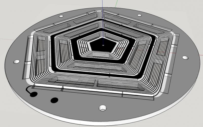
    This is a picture of an .stl file I created in Google Sketchup. It's a magnet assembly for the ECR-Ortho project that's based off a spiral conductor. The magnet assembly is sized to fit in a Denon AH-D2000 frame.

    CCA-1 the ECR-Ortho  P1130425_zps03a8d2ba

    Here's a picture of some preliminary photo-mask printing that I dabbled in. As you can see this circuit design is serpentine, not spiral.

    CCA-1 the ECR-Ortho  P1130496_zpsdb4a64af

    Here is a picture of rosin powder melted into inkjet ink printed in the form of a pentagonal spiral circuit. I was practicing on transparency hoping I'd eventually be able to use rosin powder as an etch resist.


    http://www.thingiverse.com/thing:341212
    That is a link to a thingiverse that I made which was rather unsuccessful up to this point. It is related to the CCA-1, but not quite it exactly.

    But what is it?

    The ECR-Ortho project is a dream to build -primarily via computer numerical control (or CNC) technology such as 3D printing, laser cutting, etc. in order to keep manufacturing costs down- open source headphones that can be disassembled by hand (no tools needed, no screws, etc. everything snaps together) which employ planar magnetic drivers inspired by the Sony ECR lineup of headphones. I'd currently like the circuit to be spiral, however, I believe a serpentine circuit will be easier to manufacture and implement. I'd also like to explore diaphragm material options such as Mylar, Kapton, and even elastomer-thermoplastic mixtures not too dissimilar from the urethane diaphragms found in the Micro Seiki MX-1, or AMFITON TDS-15.

    So how do I make a diaphragm?

    I'm not exactly sure how we should go about mass producing these for ourselves, but I can share with you my experiences.

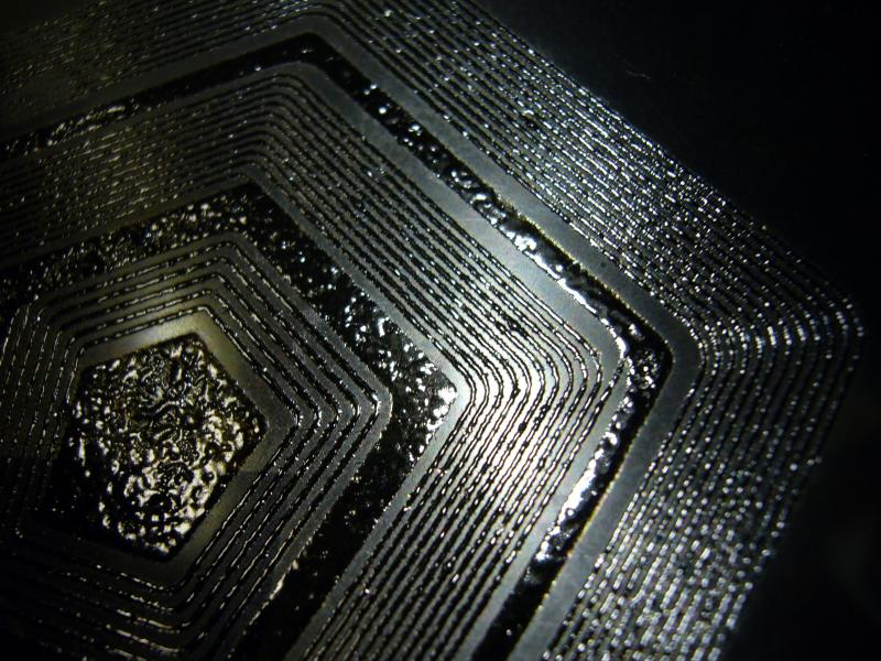
    I scanned a Bang & Olufsen U70 diaphragm and it looked great, but when I zoomed in on it it looked like a garbled up bunch of gobbledygook. I spent hours attempting to transform what was gobbledygook into a perfect Black and White image in http://www.gimp.org/. I then printed it with an old HP Laser printer onto Dupont Pyralux (Copper clad Kapton), dunked the printed image into an acid bath of Muriatic Acid (HCl), Hydrogen Peroxide (H2O2), and table salt (NaCl) and got stuff that looked like these images:

    Preliminary testing:
    CCA-1 the ECR-Ortho  B3dc0a5e_P1130663_zpsd9tapj45

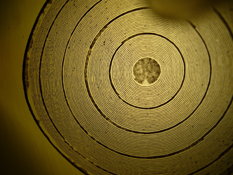
    Here you can see how the circuit is cleaner towards the center. It's because I never fully finished painting the U70 driver in Gimp. The penny is for scale and the picture was taken through a loupe given to me for free by a man named Hi.
    CCA-1 the ECR-Ortho  20f1d2eb_P1130671_zps4dqjkxy4

    Another for good measure. I've since gotten a better camera, so in the future if I experiment I should be able to pull off some better shots.
    CCA-1 the ECR-Ortho  7d8da3af_P1130665_zpsybjdlgoc

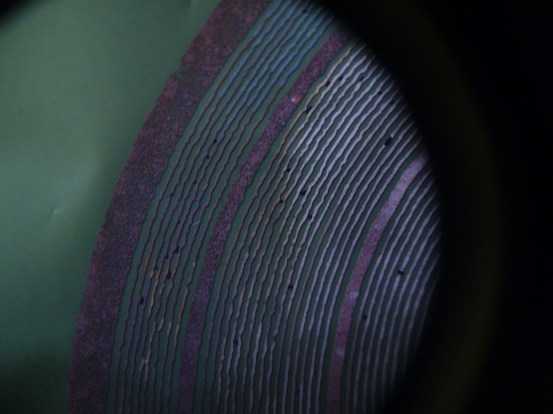
    Now, while these results look promising, I'm not sure I was using the correct acid. The fumes that were given off during etching smelled horrendous and breathing it in felt like it could melt your throat. BE CAREFUL!
    You can check out some instructables such as http://www.instructables.com/id/Is-the-best-PCB-etchant-in-every-kitchen-/ if you're concerned about using strong chemicals, but your etch times will be impacted, as will the cleanliness of your etches.
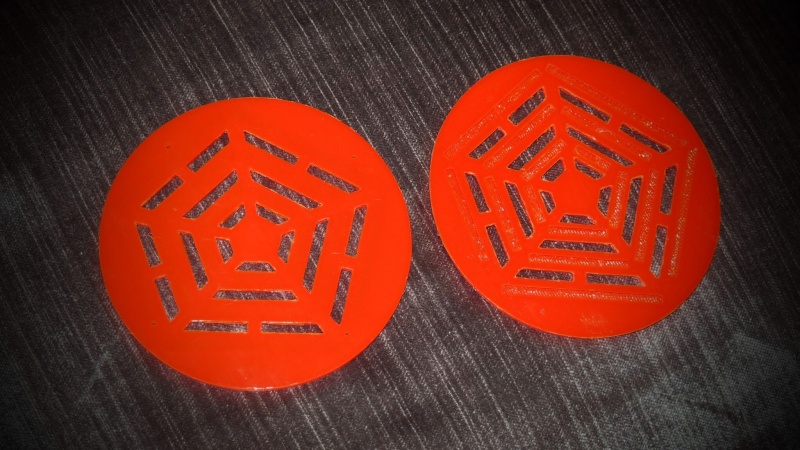
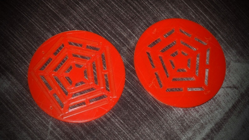

    3D printing!


    Here are the first set of 3D printed ECR-Ortho magnet assemblies. I went to 3dhubs.com and found someone (I'm sorry, I forgot your name and can't find it in my 3dhub history) who was somewhat local. The notches on the Black piece match up with the Denon AH-D2000 baffle so they could potentially be screwed into place.

    CCA-1 the ECR-Ortho  57a66f85_P1130682_zpsgnkiknkt

    CCA-1 the ECR-Ortho  B7f37d4d_P1130686_zpsclcxvl3u

    The resolution capabilities of the 3D printer that was used to print these pieces wasn't quite where I needed it to be, I think. The magnet you see in the photo below should be flush and most of the slots are too tight to even fit a magnet, I just got lucky this one could squeeze his way in for a photo. I'm not sure what happened. Did I miscalculate the width that the slots needed to be? Did I need to give the magnets a little breathing room with my calculations so that they'd slide in better? Is it the printer? Who knows?

    CCA-1 the ECR-Ortho  Caa3d168_P1130685_zpshxjnsb4b

    You can see the magnets are on the thin side. Efficiency will suffer, but I wanted to keep the overall profile of the driver down.

    Why aren't these headphones in my hands already?!

    https://cropcircleaudio.board-directory.net/t5-chi-raq-the-movie-systemic-inequality-in-englewood

    What next?

    http://www.thingiverse.com/thing:1411538/#files

    Okay, I made a new thingiverse. Files are in .stl format and ready for download, as is the spacer file (in .skp) and the circuit (in .xcf meant to be opened in Gimp).

    There are three sizes of magnets used in this build, however, I'm unsure on the quantity. If you're attempting to populate the magnet assemblies with magnets check the .stl files and count, it should be easy since there's just small, medium, and large.
    Small:1/4" x 1/8" x 1/16"
    Medium: 1/2" x 1/8" x 1/16"
    Large: 1" x 1/8" x 1/16"

    The only problem I can foresee with using PLA as our magnet assembly material is the fact that it's so brittle. If you try to screw into PLA I'm afraid it'd just just chip/crack. This means we'd have to epoxy or otherwise glue the drivers into the D2000 frame which isn't the most user-friendly, but can be dealt with. Let me know what you think as I don't have much/any experience with oriented PLA objects. If push comes to shove we could always print in PLA, cast mold the print, and then make duplicates in whatever epoxy resin we want. If we can find someone with a highly detailed ABS printer who has a lot of experience, though, this is even better, imo.
    avatar
    arty mcghee


    Posts : 4
    Join date : 2016-03-11

    CCA-1 the ECR-Ortho  Empty Re: CCA-1 the ECR-Ortho

    Post by arty mcghee Wed Mar 16, 2016 3:50 am

    CCA-1 the ECR-Ortho  Backs10
    CCA-1 the ECR-Ortho  Fronts10
    here's a couple photos of what i have
    i printed one side (left) of both pieces in pla on the heated bed at 40% fill, .1mm and a 2mm raft at very low speed
    there are some issues with the file making it difficult to print and requiring support, there are some weak areas with
    very little material, i did my best to compensate, each side took 4 hours to print, i'm not sure if this is going to work for you, take a look and if you want i will send them to you,
    khbaur330162
    khbaur330162
    Admin


    Posts : 23
    Join date : 2016-03-06
    Location : Chicago Suburb

    CCA-1 the ECR-Ortho  Empty Re: CCA-1 the ECR-Ortho

    Post by khbaur330162 Wed Mar 16, 2016 2:10 pm

    They look amazing, Arty, you did an awesome job. Very impressed. What's wrong with the files, if I can ask? I can attempt to fix it because I'm sure others who'd like to download the thingiverse and attempt prints would run into similar issues.

    As of right now the prints look good enough to try out. I can send you the magnets that I have and you can try to populate the assemblies yourself. If the stl's need tweaking we can decide where to go from there. Let me know how this sounds to you.
    khbaur330162
    khbaur330162
    Admin


    Posts : 23
    Join date : 2016-03-06
    Location : Chicago Suburb

    CCA-1 the ECR-Ortho  Empty Re: CCA-1 the ECR-Ortho

    Post by khbaur330162 Wed Mar 16, 2016 8:09 pm

    Arty, did you happen to take a look at the spacer? Is that printable, or are we looking at laser cutting, do you think?

    I've read up a bit over at diyaudio and as far as I can see Scotch-Weld 4693H is the plastic adhesive we'll most likely be looking at to glue the diaphragms to the spacers. It's supposedly a very strong, permanent bond between lots of different plastics. Tensioning the diaphragm on the other hand is a whole other beast I have not given much thought on taming, however. From what I can see it's a topic of discussion amongst many people in the DIY Stat forum over on Head-Fi and I'm guessing we'll be reading their thoughts in detail when we're ready to cross that bridge. Obviously if we were going to be assemble kits that multiple people are going to be listening to, measuring in various ways, and attempting to compare for the sake of discussing damping schemes and what have you we need to nail down a reliable method of tensioning diaphragms to the same degree over and over again.  

    Concerning the magnets, I figured I could send you a couple of each so that you have enough to populate at least one slot of each magnet combination. That's probably confusing for you, atm, it's difficult to describe. I realize the ~.2mm (or is it .02mm?) magnet dividers are much too thin to print, but as of now it at least gives you an idea of how the magnets were designed to be situated. If I need to make a jpeg in Gimp to document each and every magnet's orientation (and perhaps make a small dimple on the magnet assemblies so people can easily get a bearing on how they should even be looking at the magnet assemblies in hand before following any illustration concerning magnet orientation) I'll go ahead and do that and include the jpeg in the next thingiverse upload that I make. It won't be hard to make a color coded illustration based off the current stl files we're all looking at right now. I just want to cover all our bases. In my mind it'd be easiest to populate the magnet assemblies if the magnet slots we're a slightly tight fit for the magnets. I'd the magnets to be butt to butt for the sake of having as even a magnet field as possible where and when it's possible (ideally we'd have a few magnets custom made that decreased in size and were all our scalene pentagonal shape, but to keep costs down that's obviously not yet an option). So if the magnets are a tight fit in the slots it will be easier to glue them permanently in their new home. They'll obviously repel each other before the glue cures. Keeping the repulsion forces to a minimum and keeping those same forces as non-destructive to the gluing process as possible (hopefully we can glue the magnets in the assemblies without the need for any kind of clamping jig/s) is important if we're going to make kits which can be easily assembled by others who have less time to devote to building themselves (or others) headphones.

    This design is rather ambitious, I suppose. If it ends up being too ambitious we can explore designing a smaller serpentine, perhaps. The longest (x)" x 1/4" x 1/16" magnet I could find was 1" at the time. If this is still the case it would limit the width of our diaphragm circuit to snaking its way around 1" (if we wanted no magnets butt to butt) while it could be as tall as our ear if needed/wanted. I'm imagining something not too dissimilar from a Stax Lambda driver in moveable surface area, but perhaps slightly skinnier and about as tall when looking directly at it.
    avatar
    arty mcghee


    Posts : 4
    Join date : 2016-03-11

    CCA-1 the ECR-Ortho  Empty Re: CCA-1 the ECR-Ortho

    Post by arty mcghee Sun Mar 27, 2016 4:41 pm

    hey

    sorry i've been out of commision the past couple weeks with a serious illness
    feeling a bit better now, i won't have a lot of time for this stuff
    i don't know if this is going to work how you want it, the fit is going to be fiddly
    you have to measure each magnet to see if the vary, find a slot size that works, and compensate for shrinkage of the material printing, also the sizes differ if printed face up or face down, the side with the raised standoffs must be face down ,at 3-4 hours a print its a huge job, also i have very little modeling knowledge so i don't think i can help with that, did some tests with abs and it a real pain to get good results, its more flexible than pla but tends to delaminate, also tried some nylon which prints well and very flexible almost rubbery

    hope this helps
    khbaur330162
    khbaur330162
    Admin


    Posts : 23
    Join date : 2016-03-06
    Location : Chicago Suburb

    CCA-1 the ECR-Ortho  Empty Re: CCA-1 the ECR-Ortho

    Post by khbaur330162 Sun Mar 27, 2016 6:16 pm

    Very interesting. Nylon sounds promising. Could always print the magnet assembly in two parts? The magnet slots portion printed in Nylon if that makes sliding the magnets in easier, then have a PLA backing to support the Nylon. Not sure, just thinking out loud. "Rubbery" sounds good to me right now, tbh.

    I checked back with the website that I bought my magnets from and it looks like they stopped stocking the 1" x 1/8" x 1/16" Neo blocks. Not sure what's going on there, maybe it was just an unpopular seller, but it may or may not make life more difficult. Not going to worry about it too much at this point. Also the website used to supply tolerance information, but that info seems to be missing now. They changed the website around quite a bit. Going by memory the tolerances are tight enough from most manufacturers to, in my mind, be a complete non-issue for our purposes.

    Given material shrinkage while printing it seems as though a one-size-fits-all approach is a bit of a pipe dream for now, meaning I can't supply one set of files for everyone to download and print and have everyone expect the same results since everyone's using slightly different equipment. Kind of a bummer. Perhaps Nylon will be our answer? If it has enough elasticity to allow us to jam our magnets into their respective slots reliably, yet is still durable enough that magnets wont shift over time with strong repelling forces acting on them 24/7 it could be just what we need?

    And thank you arty, it most definitely does help. I've been stumbling around in the dark for a while now trying to build an SLA printer from scratch using the light engine from an old DLP HDTV as well as messing around with a delta style 3D printer kit I bought from China (with little to no printing success). You're light years ahead of me on the 3D printing front so everything you're supplying me right now is invaluable. If I may ask where are you located? Trying to figure out how much it'd cost for you to post whatever you're willing to give me my way.

    And glad to hear you're feeling better, don't worry about any delay. I've been working on this project's evolution for -well, it's embarrassing to say, tbh- years and this is all I've got to show for it mainly because networking with people is not my strongest suit (especially at certain times). Sad to say yet true, imo, but this project could be much further along if I was almost anybody else. Progress is in the eye of the beholder, I suppose.
    avatar
    arty mcghee


    Posts : 4
    Join date : 2016-03-11

    CCA-1 the ECR-Ortho  Empty Re: CCA-1 the ECR-Ortho

    Post by arty mcghee Mon Mar 28, 2016 1:34 am

    i'm in massachusetts
    7 bucks for all can stuff in a small flat rate box
    give it a week or 2 i'll run a test on the nylon
    its neat stuff and easy to print
    just changed the fans in my printer, its much quieter
    also got the whole thing running wireless using
    a raspberry pi, stuff is amazing
    khbaur330162
    khbaur330162
    Admin


    Posts : 23
    Join date : 2016-03-06
    Location : Chicago Suburb

    CCA-1 the ECR-Ortho  Empty Re: CCA-1 the ECR-Ortho

    Post by khbaur330162 Mon Mar 28, 2016 2:07 am

    Dang. That sounds like the future. I wouldn't have been surprised if you had left the "i'm in massachusetts" part out and ended with "I'm on the International Space Station."

    I'm imagining a battery powered, wireless, rasp-pi and Cartesian style printer, all mounted on a piece of Lucite with Pink and Blue LED's bleeding through the plastic for special effects, floating haphazardly in zero gravity while printing my headphone parts with Tan and Brown Noctua fans spinning around for good measure, possibly cooling something. And you're sipping on yogurt in a tube called Go->Gurt. I don't even know if you like yogurt... Efficiency!

    Alright, hopefully that made you laugh. But seriously that sounds awesome. So you're saying wait 2 weeks, then PayPal you $7? I think I'm missing something.

    Sponsored content


    CCA-1 the ECR-Ortho  Empty Re: CCA-1 the ECR-Ortho

    Post by Sponsored content


      Current date/time is Sun Apr 28, 2024 9:55 pm